


EXPERTISE
Naval Architecture
Reliability and Transparency in Maritime Engineering
Click the image to view full
1.Concept Design
Concept Design is developed based on the Client’s requirements of Type of Cargo, Cargo Deadweight & Ship’s Speed. The vessel’s Main Particulars are developed. Hullform Cb is determined. Resistance & Powering is worked out and Main Engines are sized. A General Arrangement is developed.
General Arrangement
The Vessel’s General Arrangement is developed by allocating the spaces suitably and optimizing the cargo spaces and accommodation spaces. The arrangement takes care of all the Safety requirements as detailed in SOLAS i.e. Space for Safety Equipments and Escape accesses.
Tank Arrangement & Machinery Space Arrangement
Cargo tanks and consumable tanks are sized and arranged to meet the functional requirements and stability requirements. Machinery spaces are sized to accommodate the various machinery as well as to control the COG. The compartmentation is carried out to comply the damage stability and load line requirements.
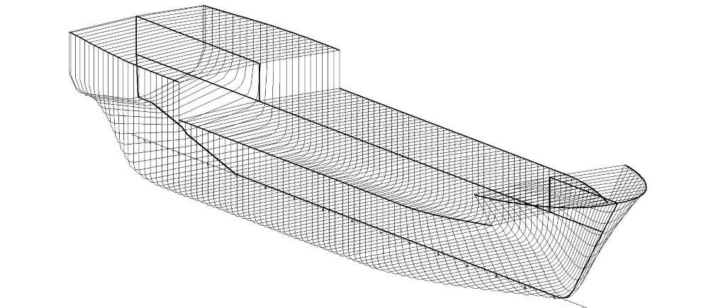
2.Principal Particulars & Hull Form
Based on a study of data on similar vessels we determine the principal particulars and develop a suitable hull form. The hull form is refined based on CFD studies. Hull form is designed to comply the required displacement and center of buoyancy. Hull form design will also comply intact stability and damage stability requirements as well as Load line requirements.
3.Weight & COG
At the FEED/Concept Design stage weight and COG is estimated and allowances are made for the uncertainties in the weight and COG. As the project progresses, weight & COG monitoring is undertaken.
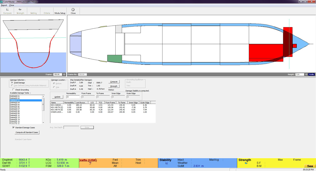
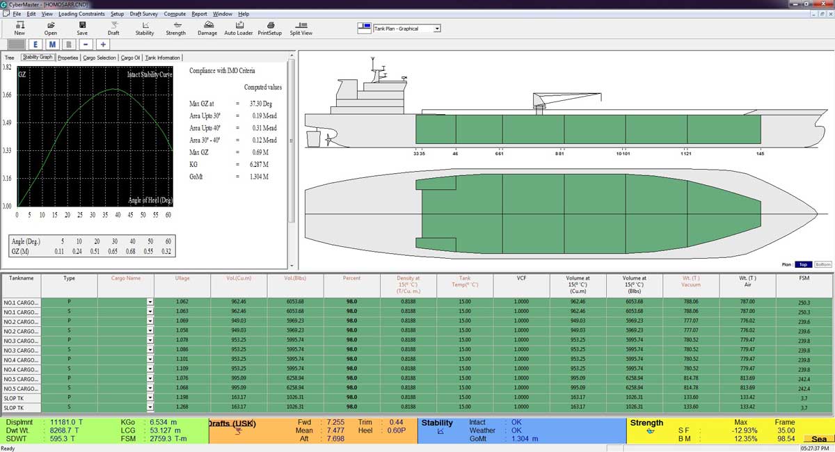
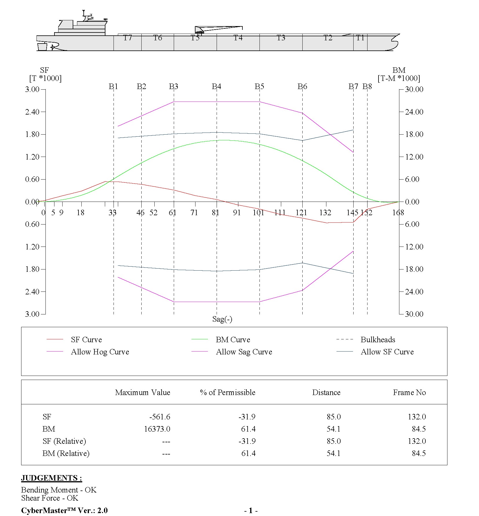
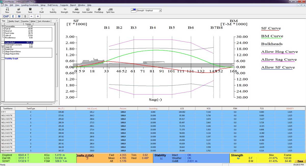
4.Intact Stability and Damage Stability
Stability compliances are achieved by proper compartmentation and by refining the main particulars. Further tank/space arrangements and weight distribution is carried out to achieve the stability requirements.
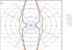
5.Motion Control
Based on sea-keeping characteristics evaluated in hydrodynamic analysis, design of the vessel is reviewed from motion control aspect. Following options are studied to improve the design of vessel using Hydrodynamic analysis
- Operating draft variation
- Breadth optimization for various operations such as crane, etc.
- Active heel control (during crane operation)
- Roll stabilizers (U tube, free surface tanks and flooding tanks, etc.)
- Weight distribution to optimize the radius of gyration of vessel
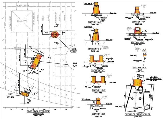
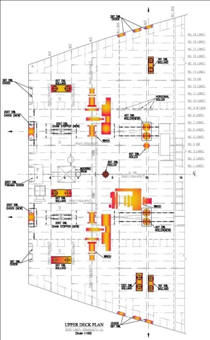
6.Mooring Analysis
Static and quasi-static analysis are carried out for any type of mooring system. Dynamic analysis is carried out in the frequency domain for both wave frequency (WF) and low-frequency (LF) motion and tension responses.
Hydrodynamic analysis based on its operating draft, weight distribution, radius of gyration (Roll, Pith and Heave) and wave heading is performed to generate Hydrodynamic and Hydrostatic parameters (Vessel mass, Added mass, Hydrostatic stiffness, Transfer functions for first order wave induced motion and wave drift coefficients) required for mooring analysis.
Appropriate Mooring Pattern
Based on mooring analysis appropriate mooring pattern is developed /recommended.
Mooring Line Specifications
Based on mooring line tensions (pretensions) comprising of static component (arising from wind, wave and current), wave frequency component (arising from first order wave loads) and low frequency component (arising due to second order wave loads and wind dynamic) which are calculated from mooring forces (including steady force, slow drift mooring force and wave frequency motion) along with environmental forces, mooring line size (based on required minimum breaking load) & length, Anchor size & location and loads on turret are calculated.
Vessel Excursion
Vessel excursion under the action of all external forces is calculated.
Mooring Winch Capacities
Mooring winch capacities are determined and a layout is developed based on mooring line tensions and excursion of the vessel.
- Concept Design
- Principal Particulars & Hull Form
- Weight & COG
- Intact Stability and Damage Stability
- Motion Control
- Mooring Analysis